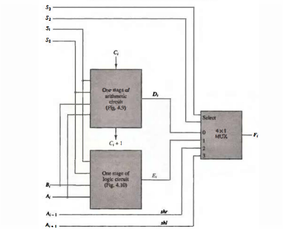
The arithmetic, logic and shift micro operations which are discussed in previous are combinely implemented as one unit called arithmetic logic shift unit (ALU). Instead of having individual registers performing the micro operations directly, computer systems employ a number of storage registers connected to a common operational unit called an arithmetic logic unit, shortly called as ALU. To perform a microoperation, the contents of specified registers are placed in the inputs of the common ALU. The ALU performs an operation and the result of the operation is then transferred to a destination register.
Inputs Ai and Bi are applied to both the arithmetic and logic units.Based on the input of the selector lines S1 and S0 the perticular micro operation is selected.Based on the selector lines S2 and S3 the output of the multiplexers is decided.The inputs of the multiplexers are output of arthematic , logic and the other two data inputs to the multiplexer receive inputs Ai-1 for the shift-right operation and Ai + 1 for the shift-left operation.
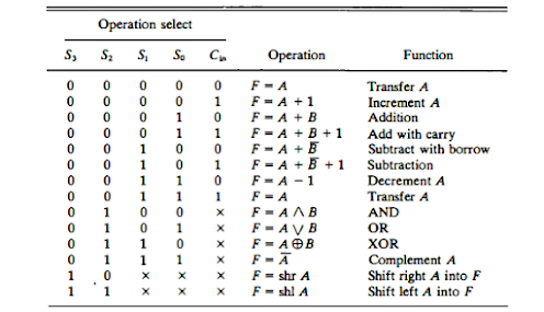
The circuit whose one stage is specified in above figure. provides eight arithmetic operation, four logic operations, and two shift operations. Each operation is selected with the five variables S3, S2, S1, S0, and Cin .The input carry Cin is used for selecting an arithmetic operation only.
Below Function Table lists the 14 operations of the ALU.
- The first eight are arithmetic operations and are selected with S3 S2 = 00.
- The next four are logic operations and are selected with S3 S2 = 01. The input carry has no effect during the logic operations and is marked with don't-care x's.
- The last two operations are shift operations and are selected with S3 S2 = 10 and 11. The other three selection inputs have no effect on the shift.


0 comments :
Post a Comment
Note: only a member of this blog may post a comment.